Disc Springs

Associated Spring offers the Clover®Dome a conical formed disc spring that utilizes stress-relieving cutouts on both the inner diameter and the outer diameter. These patented cutouts allow the Clover®Dome to achieve two to three times the deflection of current disc springs. This added deflection makes the Clover®Dome suitable in applications where disc springs fall short of desired deflection or where the space occupied by coil springs is not tolerable. Clover®Dome can also be stacked in a variety of methods to achieve force versus deflection (FD) curves that are not possible using a single spring.
Applications of these precise solutions include valves, clutches, disc brakes, swivel designs, bus bar connections, bolt tension control, clamping fixtures, shock absorption, turret tools, die strippers and die seats.
Upgrade Your Valve Performance
Technical Data
The Clover®Dome is very different from similar spring washer products. The Clover®Dome is a conical formed disc spring that utilizes stress-relieving cutouts on both the inner diameter and the outer diameter. Its overall height is roughly 10% of its diameter. The height of a Belleville washer is only 3% of its diameter. This translates in two to three times more deflection to work with. The result is a spring rate lower than that of a stiff Belleville washer, but significantly higher than the spring rate of a coil spring, for an equal amount of deflection. When compressed to 75% of its height the Clover®Dome “recovers” to its original height and does not flatten out.
Click on the sections below to learn more about the Clover®Dome difference.
Geometry of the Clover®Dome
 |
Figure 1 illustrates the basic geometry of the spring, essentially a continuous clover-shaped ribbon of equal width (W) and formed into three equally spaced disc segments (S) which can deflect radially when side-stressed (F) at the aperture or vertically, when formed into a dome. Characteristic of Clover®Dome geometry is the relationship of radial point P1 at the inner edge of the disc’s outer segments (S) to radial point P2 at the inner edge of cutouts (A). For standard dome, P2 is located on or inside the diameter determined by the radius at point P1. |
Clover®Dome Spring Rates
The unique spring rate of the Clover®Dome bridges the large gap between very stiff Belleville disc springs and resilient coil springs. To demonstrate the different spring rates between Clover®Dome, Belleville, Curved, Wave and Finger springs, a simple equation referred to as “Coefficient of Compliance” (CC) is shown in Table 1. The Coefficient of Compliance (CC) can be determined by experimental means or if the material thickness has been determined.
The equation below shows how to calculate the CC when the material thickness has previously been determined. Generally the CC is approximated using data derived experimentally. The CC is a relative method for comparing springs. The common disc spring is stiffer and would have a very low CC while highly compliant coil springs will have a higher CC. The coefficient is calculated as follows:

Deflection
The angle of the conical form will determine the amount of total deflection the Clover®Dome will yield. This cone angle is dependent upon the ratio of the OD to the ID and the thickness of the material. Testing has shown that as material thickness increases the cone angle decreases. OD to ID ratios of 2.0 will also yield a lower cone angle when compared to OD to ID ratios of 2.5 and higher. The actual cone angle is difficult to predict and these calculations should only be used as approximations. The following figure is a guide to approximating the height of the formed part. OD to ID ratios approximately 2.0 with material thickness greater than .030” should use an angle of approximately 13º. While OD to ID ratios of 2.5 and greater with material thickness less than .030” should use angles of approximately 14º.

Spring Rates
The desired spring rate is used for calculating the material thickness. To determine the spring rate we must know what the desired loads are for the Clover®Dome as well as the OD and ID. First we must determine the amount of deflection a particular OD and ID combination will generate. This can be determined from the previous section on calculating deflection. Once the deflection is calculated we can then determine the spring rate by dividing the desired load by the calculated deflection. This will approximate the spring rate as if it were linear. We know from figure 3 that the spring characteristics are very often non-linear. This approximation is necessary to calculate the properties of the Clover®Dome. This spring rate is theoretical and should only be used to approximate designs.

Force vs. Deflection Curves
The shape of the force versus deflection curves (FD curves) can be approximated using figure 3 below. The ratio h to t is used to determine the shape of the particular curve. Ratios of 3.5 and higher yield a regressive curve while ratios of .5 yield a progressive curve.

Series Stacking
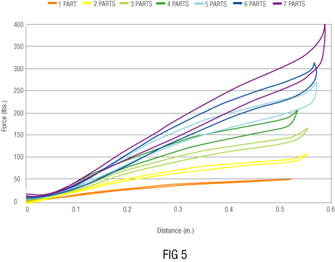
Series stacking of Clover®Domes is utilized when the deflection of a single spring is not sufficient. Equation 3 illustrates the effects of placing Clover®Domes in series stacks. The force for the stack remains constant while the number of parts in the stack multiplies the deflection.


Parallel Stacking
Parallel stacks of Clover®Domes can be used to achieve forces that cannot be reached using single springs. Equation 4 illustrates the effects of adding springs in parallel. The force of each spring added to the stack is added to the total load while the total deflection of the stack remains constant.


Material Thickness
The thickness of Clover®Domes is calculated using the spring rate, approximated CC and the OD. The following equation shows how to determine the material thickness required.
![]()
There are limitations to material thickness. Pre-tempered material, that is required for the Clover®Dome, is available in thicknesses up to .060” (1.52mm). Generating parts thicker than this is generally avoided. At this time designing parts over .050” (1.27 mm) should be avoided due to manufacturing limitations and material availability. Figure 6 (below) is an example of the variation in FD curves for parts with the same OD/ID and varying thicknesses.


Deduction
The trend of force / deflection curve for a thick “t” disc tends to be linear. For a thin “t” disc the curve is linear for the first portion of the curve but tends to flatten out and regress at its apex.

Friction & Hysteresis
Friction is generated when Clover®Domes are in contact with any other surface. The friction is roughly equivalent to 3% of the total load. When stacking Clover®Domes friction of each part stacked in parallel is taken into account. The friction generated by series stacks is much lower than parallel stacks. Hysteresis is the difference in force from loading to unloading. Hysteresis results in an increase in force during loading and loss of force during unloading. Figure 7 illustrates hysteresis, which can be equivalent to 3% of the maximum force. The effects can be reduced using lubrication on the friction surfaces.

Specifications
In considering a Clover®Dome disc spring application, it is important to ask the following questions:
- Size limitations on OD & ID
- Space limitations, max height (O.H.)
- Pre-load (load at initial deflection)
- Final load (load at full deflection)
- Initial deflection (measured from O.H.)
- Distance from initial to final deflection
- Static or dynamic application
- No. of cycles if dynamic
- Environment (Chemical, temperature)

We appreciate your interest in the Clover®Spring line of products!
Instead of < and > please use “less than” or “greater than”; instead of / use “-” or “;” to separate values


